Ralph Dyck’s 1970s Home-Brew Synth Rescued from Pawn Shop
OK, so this isn’t directly related to the MC8, but it involves Ralph Dyck, and it’s a cool story, and it’s high time that I update this blog, so here ya go!
A couple years ago, Ralph mentioned to me that in the early-70s he had built a couple of custom analog synthesizers for local schools – UBC and Carson Graham Senior Secondary. I attempted to contact the music departments of both of these schools. The UBC music department still had theirs, but the Carson Graham synth was missing in action. Fast forward to a few weeks ago, and I get an email from Ralph that an acquaintance of his in Vancouver recognized Ralph’s handiwork in a craiglist ad for a homebrew synth- it was the long-lost Carson Graham synth!

The asking price was only $75, but try as he might to recover it, Ralph was too late, and it was purchased by a young guy interested in making “bloopy synth sounds.” Fortunately, the shop owner agreed to pass on guy’s contact info to Ralph, and after much back and forth email negotiation, we managed to procure the synth (for a not-too-crazy price), and Ralph has been hard at work trying to get it back into working order (sans schematics). Here’s a brief interview with Ralph, some pics, and some sound clips:
Q: Can you tell me a bit about the history of this synth, why it was built, and how you arrived at its design?
Ralph: I had made some friends at UBC in the music department and they all knew about the synthesizer I had made in 1971. One of those friends was Rob Carr who became a music teacher at Carson Graham Senior Secondary (high school). He was able to get the school to budget some money to build a small synthesizer for the music department. Remember, in those days there were no low cost synthesizers on the market, just big modular systems like Moog, Arp and Buchla. In fact, a friend of mine, maybe that year, bought a MiniMoog and asked me to have a look at it, I’m not sure about the timing. Rob Carr gave me his budget figures and I figured out what I could make for him. He got some money so I could start to buy parts, I had an account at the largest electronics store in Vancouver and bought all of the opamps, transistors, resistors, capacitors, connecters etc. I had a plan and that was to make a subset of my own synth that I had built. I figure that this must have been early 1972 because of where I was living at the time, I had started to work jazz gigs with the Paul Horn Quintet then as well. It was an operation on the cheap, a piano player working in the landlady’s basement breadboarding circuits and testing them. Some of the designs are quite different from the circuits I had already done the year before. I’ll get into that next. I can’t give an accurate timeline for building this synth but it certainly took 3 months or so, I guess. I think that we were all a bit excited by having this system as the first synth in a high school here.

Q: Can you give a detailed rundown of the various components and signal flow of the synth?
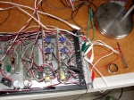
Ralph: Once the synth had been delivered to my apartment I could see right away that the patching had been heavily modified by someone at the school, I guess. I’m sure that they wanted to make it more sturdy and professional by using rack mount telephone patch bays, the ring-tip and sleeve types, like the old telephone exchanges. They were built to take a lot of use and abuse.
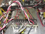


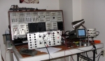


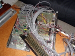


The Main unit I’ll call Rack 2, because that’s what I’ve called it the past week, Rack 1 is an auxiliary unit. Rack 2 has, left to right, a PreAmp and Low Pass Filter on a vector board, hand wired. I imagine the PreAmp is X10 so, the Filter has 3 switchable ranges and is not voltage controlled, I guess, to cut costs and I hadn’t finished the design of my VCF yet, it was to have Low Pass, Band Pass, Notch and High Pass at 12db/octave with resonance.
To continue, there are 3 circuit boards, 2 hand wired vector boards and one pc board. The vector boards are the Sample and Hold clock and the Ring Modulator. The pc board is the Sample and Hold. To the right of them is the VCA which has a pc board but doesn’t work, probably a bad 741 opamp, static was a big problem for the outputs of 741s, too easy to blow them up. To the right of the VCA is the ADSR Envelope Generator which is the first circuit that I designed without any help from my engineer friends, I was proud of that, done the year before. The same thing I fear happened to its output which was dead. However, by searching on the pc board I found a completely intact envelope signal that was attenuated by a factor of 12. Well, I thought, I’ll amplify it and put it out which is what I did with an LF353 dual opamp. We’ll have to put in a VCA kit to replace the one there and all of the synth will be complete. To the right of the ADSR are the 2 simple VCOs with Triangle and Square Wave outputs, they work perfectly.
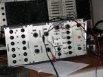
Rack 1 is an auxiliary unit that has, left to right, a 6 input, stereo output mixer and a white noise generator, all built on a hand wired vector board. It is followed by a Stereo Hammond Spring Reverb pc board of which the Left channel is dead! Who knows what the problem is, I spent hours trying to make the Left channel work and had no idea what the wiring was, then I tried the Right channel, it worked perfectly the first time! Murphy Lives.
To the right of the reverb is the full VCO which is the type that I built for my own synth. It is .02hz-20hz and 20hz-20khz with Sine, Triangle, Sawtooth, Square and VC Pulse outputs, all waveforms are available separately and mixed together. The waveforms are switchable from ± 5volts for audio and to 0-10volts for control purposes, the VCO is 1volt/octave (as are the Rack 2 VCOs).
On the right hand side of Rack 1 are the 20 holes for my 1/4″ jack socket patch bay and replaced by a 24 connector terminal block which was connected to the telephone patch bays. I wish they wouldn’t have done that. Well, the synth was made for experimenting by the students, I’m sure that it was a huge job to put in the patch bays and rack mountings and making sure that electrically everything was correct.
A simple patch might be to connect the White Noise to the PreAmp and PreAmp to the Sample and Hold input. Connect the Sample and Hold output to the VC inputs of the 2 simple VCOs. Connect the VCOs to the 6 input Mixer and do a Left/Right channel thing with the mixer pots. Connect the Sine wave output of the full VCO on Rack 1 to the VC inputs on the VCOS in Rack 2. Use the ±5volt Sine at a low frequency to modulate the simple VCOs. Play with it! Remember, there’s no VCA so we can’t use the ADSR and the synth will sound all of the time. I almost forgot the Power Supply which is ± 15 Volts at 2 amps, it’s output is exact after 40 years! Here’s some very basic demos of what the functioning components of the synth currently sound like:
Q: Can you give a summary of the current state of the synth, ie what works, what doesn’t, and what needs to be replaced?
Ralph: Everything works, amazingly, EXCEPT the VCA and the Left channel of the Stereo Reverb. The ADSR has a small circuit attached to provide a proper output. A VCA module in kit form would be perfect for this, it must be ± 15volt supply, 6db/volt or linear and ± 5volts audio output. The reverb Left channel can be fixed but it must be taken apart and probed to find out which opamp is dead. Use the Right channel as a guide, it’s the same.
Thanks to Ralph for this quick interview, and as soon as the synth is in fully restored condition, we’ll update the blog with further details, video, sound clips, etc!
8 Comments »
Leave a comment
About

This blog will be an information resource for the 1977 Roland MC-8 Micro-Composer, the grand-daddy of all modern digital sequencers. I won’t be able to offer any comprehensive tech support here, but hopefully over time there will be enough info accumulated to get you going. Please stay tuned while I gradually add stuff!
In the meantime, a good intro to the MC-8 may be found in the article that Chris Carter wrote for Sound On Sound Magazine in the late 90s.
-
Recent
- Roland MC-8 MicroComposer Vintage Sequencer Repair
- Roland MC8 vs Arp Axxe – ODD RHYTHMS – Ralph Dyck
- Roland MC-8 Sequencer Malfunction w/ Sequential Pro-One Synth
- Making a Roland MC-8 Cable
- Low Serial Number “Blue Meanie” MC8
- RIP Ralph Dyck, Sept 28, 1941 – May 20, 2013
- Ralph Dyck: My Commercial Life using my handmade sequencers prior to the MC-8
- Interview: Richard James Burgess of Landscape
- Ralph Dyck Reunited With Another Long-Lost Synth Creation
- Ralph Dyck’s 1970s Home-Brew Synth Rescued from Pawn Shop
- 1972 Newspaper Article about Ralph Dyck & His Modular Synth
- Giorgio Moroder w/ MC-8 & System 700 via Sound On Sound Magazine
-
Links
-
Archives
- February 2018 (2)
- February 2016 (1)
- January 2016 (1)
- June 2013 (1)
- May 2013 (1)
- January 2013 (1)
- December 2012 (1)
- July 2012 (1)
- February 2012 (1)
- March 2010 (2)
- February 2010 (13)
- January 2010 (35)
-
Categories
-
RSS
Entries RSS
Comments RSS

wow. great story and a very nice bit of synth history. i would like to visit that pawnshop, or other pawnshop. could you please provide some addresses?
my email is hieronimbus@yahoo.com
cheers!
joe.
🙂
Wow! That is crazy! It’s one of those ‘patience plus time equals wish fulfillment’ situations – I love it when that happens!
I found that in the pawnshop and called Ralph.. i didn’t know what it was when i looked at it but I knew it was made by someone who knew what they were doing.. the panel said RDE on it.. i went home and thought about it for about 30 mins and it occurred to me that it was perhaps Ralph.. by the time he got to the pawnshop it had been sold.
funny.. it was listed on craigslist as a “buchla electronic music system $75” i RACED to the pawnshop and by the time i got there the phone was ringing off the hook.. i was a little annoyed that it wasn’t a buchla and had to rip back home to grab some instrumentation for a show i was playing that evening.. i am glad ralph finally got to see it again.
-rick
[…] by the recovery of his Carson Graham synth, Ralph went in search of another synth he made around the same time for the UBC. Bob Pritchard of […]
Pingback by Ralph Dyck Reunited With Another Long-Lost Synth Creation « Roland MC-8 Micro-Composer | July 25, 2012 |
Man – that’s just wonderful. I was a student at Carson Graham, and was able to take the “21st Century Sound” class (yes, that’s what it was called) with Rob Carr in 1973-74, and I have always wondered what happened to the “Ralph Dyck Enterprises” synthesizer we used. For years, I had a quarter-inch tape reel of my compositions – until I realized that I would probably NEVER own a 1/4″ reel-to-reel machine. It was a great piece of kit, and I am glad it finally came home.
So glad to hear it working, hope you’re having fun with it!
From the guy who wanted to make bloopy sounds with it.
I was fortunate enough to have taken 21st Century Sound at Carson Graham during grade 11 and 12. IT was a fantastic course that taught me so much. The RDE synth was an amazing way to access and understand synthesizers and how LFO’s worked, how filters worked. So happy that this was saved!
I’m amazed at the interest in something I did more than 40 years ago! To the students of the 21st century sound courses I give all of my respect for having dealt with my machine! The Carson Graham Synth (CGS) was an experiment because I did not have the budget to make it like my own synth. What I don’t have is the simple calculator keyboard that I used as a controller of the CGS. The CGS was never meant to be used as a standard musical instrument as my own synth was, it was meant to show how sounds were made and modified, as a teaching tool. My thanks go to Rob Carr who pushed me to make it! I’m an old guy now but with this I have many memories from that time.
Ralph, 2/13/2013. Vancouver.